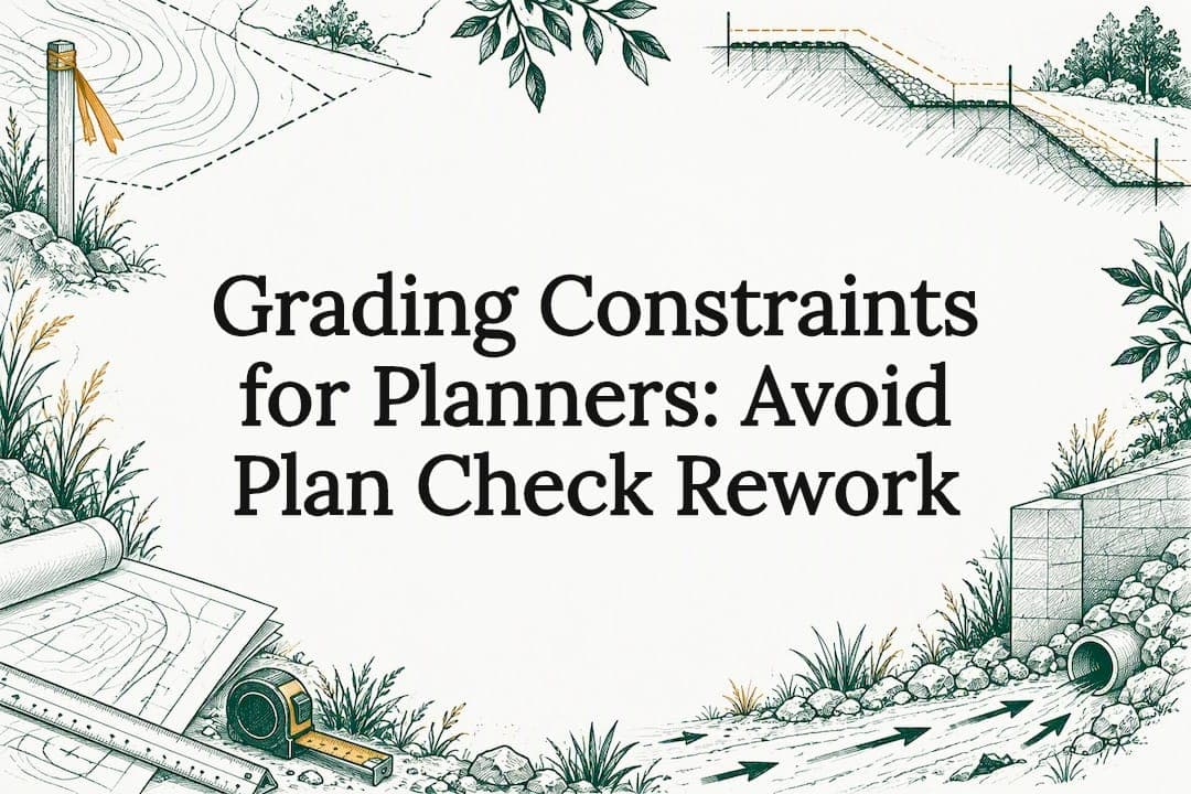
A grading constraint is a defined area that prescribes minimum and maximum slopes plus flow direction within a site plan. Before setting one, secure a topographic survey and geotechnical inputs, then map the constraint area against sensitive features and setbacks. Most jurisdictions tie these settings directly to permit and plan-check requirements, so getting them right early avoids rework later.
TL;DR:
- Near foundations, require a 6 inch fall within the first 10 feet, about a 2% slope; impervious surfaces typically use the same minimum.
- Permit thresholds vary: Seattle cites grade changes above 3 to 4 feet and earthwork above 50 to 500 cubic yards; sensitive areas can lower limits to 25 or 50 cubic yards.
- Before submission, show spot elevations at every pad corner and low point, route drainage arrows to an approved facility, and include final grading certification.
- Require a geotechnical report for cuts or fills steeper than 1.5:1 or involving retaining walls, and base final slope limits on site soil conditions.
- Run the grading solver with direction lines active before fixing slope values, then coordinate flow paths with stormwater facilities and utility routes.
Table of Contents
- Grading Constraints Versus Editing Surfaces Directly
- Numeric Slope Criteria and Typical Thresholds
- Permit Triggers and Checklist Items Before You Submit
- Developing and Validating Grading Constraints Step by Step
- A Pre-Submittal Checklist to Cut Review Cycles
- How We Build Grading Constraints Into Feasibility and Master Planning
- Challenges by Soil Type and Climate, and How to Mitigate Them
- Integrating Grading Constraints With Stormwater and Erosion Control
- How Grading Constraints Shape Infrastructure and Utility Placement
- Grading Constraints Across Phased or Multi-Stage Developments
- Why Grading Constraints Deserve Attention Earlier in Design
- Where Urban Planning Pros Fits Into Your Grading Work
- FAQ
- Sources
Grading Constraints Versus Editing Surfaces Directly
A grading constraint is a polygon drawn over a design surface that locks in minimum and maximum slope values, plus a direction line that tells the grading solver which way water or a finished grade must flow. Instead of hand-editing every triangle on a surface model, we define the rule once and let the solver apply it across the polygon. This matters most where existing elements need protection: a mature tree canopy, a utility easement, or a neighboring parcel's drainage path.
Constraints also integrate directly with grading optimization tools; for large earthwork projects, coordinating a commercial insurance plan for property developers helps manage risk and compliance. Vendor documentation for grading constraints describes polygonal constraint areas, slope min and max settings, and direction lines used to control solver behavior without remodeling existing geometry.
Typical uses include:
- Protecting a steep natural slope from unintended cut or fill.
- Holding a flat pad at a fixed elevation near a building footprint.
- Forcing flow toward an approved stormwater facility instead of a neighboring lot.
- Limiting disturbance inside a wetland buffer or easement corridor.
Numeric Slope Criteria and Typical Thresholds
Reviewers look for specific numbers, not general intentions. The most common rule for grading near structures requires a 6 inch fall within the first 10 feet away from a foundation, or roughly a 2% slope, a standard referenced in Fairfax County's subdivision grading checklist. Impervious surfaces such as driveways and walkways typically carry the same 2% minimum to prevent ponding.
A 6 inch fall within the first 10 feet of a foundation (about 2%) is one of the most widely cited municipal grading standards, according to Fairfax County's grading checklist, and it shapes how constraint polygons get drawn near every structure on a site.
On the maximum side, slope ratios drive both stability and permit requirements:
- A 3:1 slope (about 33%) is a common threshold for requiring stabilization or a geotechnical report on cuts and fills.
- A 4:1 slope (25%) often marks the point where manufactured slopes need special review in municipal grading codes.
- Stormwater facility side slopes are frequently capped at 5:1 for irrigated grass and 3:1 for landscaped areas, per Phoenix's grading and drainage checklist.
- Slopes intended for mower or maintenance access generally stay at 4:1 or flatter.
Setting a constraint steeper than these thresholds without planning for stabilization is one of the fastest ways to trigger a plan revision.
Permit Triggers and Checklist Items Before You Submit
Grading permit thresholds vary by jurisdiction, but the pattern is consistent enough to plan around. Seattle's grading permit guidance/grading-permit) lists vertical grade changes beyond roughly 3 to 4 feet, earthwork volumes above 50 to 500 cubic yards, permanent slopes steeper than 3:1 or 4:1, and disturbed areas of 5,000 square feet or more as common triggers. Work inside environmentally critical areas or special flood hazard areas can drop those thresholds significantly, sometimes to 25 or 50 cubic yards.
Before submittal, confirm these items are ready:
- Existing and proposed topographic surveys with spot elevations at pads, low points, and adjacent lots.
- A drainage statement describing flow patterns and discharge points.
- A geotechnical report for any cut or fill steeper than 1.5:1 or involving a retaining wall.
- Stormwater management or best management practice notes tied to approved facilities.
- Compaction specifications for controlled fill, especially under foundations.
- Certification from the Professional Engineer of Record on the final grading sheet.
Scheduling a pre-application meeting with the reviewing jurisdiction, where one is offered, resolves ambiguity about which thresholds apply before time is spent on a full submittal package. Seattle's own guidance recommends a pre-application site visit for larger disturbances specifically to identify code limits early.
Developing and Validating Grading Constraints Step by Step
Building a constraint set that survives plan review follows a sequence, not a single drawing pass.
- Collect topo, utility, and geotechnical data. A licensed surveyor provides existing topography and boundary data; a geotechnical engineer provides bearing capacity, soil classification, and slope stability recommendations.
- Map constraint polygons against sensitive features. Overlay easements, buffers, floodplain limits, and existing structures, then draw constraint boundaries that respect each one.
- Assign slope min and max values and direction lines. Configure the grading solver with the numeric thresholds from municipal checklists, flagging any polygon that needs a fixed flow direction toward an approved outlet.
- Iterate with retaining walls, swales, and stormwater elements. Run the solver, check for conflicts, and adjust constraints where a wall or swale is the more buildable answer than a steep cut.
- Run a quick plan-check against the municipal checklist. Confirm spot elevations, drainage arrows, and geotechnical certifications are all present before the formal submittal.
Pro Tip: Run the grading solver with direction lines active before finalizing slope values; catching a flow conflict in this step is far cheaper than catching it after a reviewer redlines the plan.
This sequence keeps the geotechnical and survey data driving the constraint values, rather than the other way around, which is the most common source of rework we see on resubmittals.
A Pre-Submittal Checklist to Cut Review Cycles
A short checklist applied before submittal catches most of the redlines reviewers issue.
- Spot elevations shown at every pad corner, low point, and adjacent lot line.
- Drainage arrows tracing flow to an approved stormwater facility, not an undefined offsite point.
- Sump pump discharge points shown at an adequate distance from foundations and property lines.
- Compaction and controlled-fill notes included wherever fill supports a structure.
- Stabilization called out explicitly for any slope at 3:1 or steeper.
| Common failure point | Quick fix |
|---|---|
| Missing spot elevations at pads | Add elevations at every pad corner and low point before submittal |
| Unresolved offsite flow | Route drainage arrows to a named, approved facility |
| Improper sump or roof discharge | Confirm discharge distance meets the local standard |
| No geotechnical certification on steep cuts | Attach the certified report for any slope steeper than 1.5:1 |
Confirming easement locations, utility positions, and building pad certification procedures alongside this checklist closes most of the gap between a first submittal and an approved one.
How We Build Grading Constraints Into Feasibility and Master Planning
Our process starts with a topographic survey before a single constraint polygon gets drawn. Survey data and geotechnical findings feed directly into constraint boundaries, which then shape how grading coordinates with drainage design from the earliest concept layout rather than being bolted on afterward.

This sequencing catches conflicts most teams find much later: a retaining wall that surprises the budget during construction, or a drainage path that fights an adjacent parcel's grading. Addressing these inside a development feasibility study means the constraint work happens while a project's direction is still flexible, not after entitlements are locked and a redesign carries real cost.
Challenges by Soil Type and Climate, and How to Mitigate Them
Soil conditions change what a grading constraint can reasonably demand. Expansive clay soils shift with moisture, so a slope that looks stable in a geotechnical report during a dry season can move during a wet one; constraints in these soils often need flatter maximum slopes and wider setbacks from foundations than the general 3:1 guidance suggests. Sandy or granular soils drain faster but are more prone to erosion on exposed cut faces, which pushes constraint direction lines toward faster, more direct conveyance to an approved outlet rather than sheet flow across open ground.
Climate adds a second layer. Sites in high-rainfall regions need constraints that assume larger peak flows and may require steeper minimum slopes on impervious surfaces to avoid ponding during short, intense storms. Sites prone to freeze-thaw cycles need extra attention to slope stability calls on cut faces, since repeated freezing can loosen material that passed a geotechnical test taken in a different season.
The mitigation pattern is consistent across these variables: let the geotechnical report, not a generic slope table, set the final numbers for a specific site. A 3:1 maximum slope is a reasonable starting assumption almost everywhere, but a geotechnical engineer may flatten it considerably on expansive clay or in a high-rainfall zone. Building that flexibility into the constraint polygon from the start, rather than treating the geotechnical report as a late check, avoids the redesign that follows a failed stability assumption.
Integrating Grading Constraints With Stormwater and Erosion Control
Grading constraints and stormwater management work best as one coordinated system rather than two separate drawings layered on top of each other. The direction lines inside a grading constraint determine where water goes, which means they need to point toward the same stormwater facilities shown on the drainage plan, not a generic downhill direction.
Erosion control depends heavily on the same slope values a grading constraint sets. A cut face steeper than 3:1 that lacks a stabilization note is a common redline specifically because erosion control measures, whether seeding, matting, or a retaining structure, depend on knowing the final slope before they can be specified. Phoenix's grading and drainage checklist ties side-slope limits for stormwater facilities directly to maintenance access and erosion risk, capping irrigated grass slopes at 5:1 and landscaped slopes at 3:1 for exactly this reason.
Validating grading against stormwater performance early, rather than after a surface is finalized, also reduces the chance of failing a plan review tied to storm event requirements. Practitioner experience across municipal review processes consistently points to the same lesson: a constraint set that ignores the stormwater model tends to require a second round of grading once the drainage engineer catches the mismatch. Building both disciplines from the same topographic base file keeps the slope values and the flow paths in agreement from the first iteration, which is the fastest way to a clean plan check.
How Grading Constraints Shape Infrastructure and Utility Placement
Grading constraints do not just control slope, they determine where utilities and infrastructure can physically sit. A constraint polygon that holds a steep natural slope in place also limits where a gravity sewer line can run, since gravity systems depend on consistent fall along their length. When a constraint flattens a grade to meet a 2% minimum near a building, that same flattening often shifts where a storm drain inlet or a utility trench needs to sit to maintain its own required slope.
Road and access layouts feel this most directly. A maximum slope constraint set at 4:1 for a vehicle access path limits how steeply a road can climb across a site, which in turn shapes where intersections, driveways, and utility crossings land. Retaining walls introduced to hold a steeper slope inside a constraint boundary also compete for space with utility corridors, since a wall footing and a buried utility line both need setback distance from each other.
Coordinating constraint polygons with utility routing early, rather than finalizing grading first and routing utilities second, avoids a common conflict: a utility trench that needs a specific minimum slope running directly through a zone the grading constraint has already flattened or steepened for a different reason. Resolving this during constraint development, while slope values are still adjustable, costs far less than relocating a utility line after construction documents are issued.
Grading Constraints Across Phased or Multi-Stage Developments
A phased development adds a dimension that a single-phase project does not have to manage: the grading constraints for an early phase have to anticipate the grading needs of a phase that has not been designed yet. A constraint polygon drawn to hold a slope in Phase 1 can become a problem in Phase 2 if the later phase needs a different flow direction or a different pad elevation at the shared boundary.
Temporary slopes are a common tool here. A constraint might allow a steeper, temporary grade along a phase line with the understanding that the slope gets regraded once the adjacent phase begins construction, rather than building a permanent retaining wall for what is really an interim condition. This keeps early-phase costs lower without creating a permanent slope that exceeds stability thresholds.
Drainage direction lines need the same forward look. Water routed to a temporary detention area in Phase 1 often needs to redirect toward a permanent stormwater facility once Phase 2 or 3 comes online, so the constraint direction lines in the first phase should be documented as temporary rather than treated as the final design. Utility stubs left for future phases also need grading constraints around them that protect the stub elevation until the next phase connects to it.
The projects that handle phasing well treat the master grading plan as the single source of truth across all phases, with each phase's constraints pulled from that master plan rather than designed in isolation. That approach keeps a later phase from inheriting a grading conflict that an earlier phase's reviewer never had reason to catch.

Why Grading Constraints Deserve Attention Earlier in Design
Grading constraints work best as a design driver, set before layout decisions harden, rather than as a compliance step added once a site plan is nearly finished. Treating slope and drainage limits as fixed early data points, the same way a zoning setback is treated, prevents the layout changes that come from discovering a steep slope or a flow conflict after the rest of the plan is drawn. Feasibility work benefits most from this sequencing, since it protects an owner's decision before capital is committed to a design that the ground cannot actually support.
— Jeremy Wenger
Where Urban Planning Pros Fits Into Your Grading Work
We scope feasibility studies, grading and drainage coordination, and surveying together, because a grading constraint is only as good as the survey and geotechnical data behind it.
A typical engagement starts with a topographic survey and a feasibility review, then moves into master land planning once constraint boundaries and permit thresholds are clear. If you want a project snapshot before committing to a full design, reach out through our services page to discuss scope and next steps.
FAQ
What are construction constraints?
Construction constraints are physical, regulatory, or site-specific limits that restrict how a project can be built, including slope limits, setbacks, easements, soil conditions, and permit thresholds. Grading constraints are one specific type, focused on slope and drainage direction within a defined area of the site.
What's the difference between leveling and grading?
Leveling typically means flattening a surface to a single consistent elevation, while grading means shaping a surface to multiple elevations and slopes to control drainage and meet design requirements. A grading plan almost always involves varied slopes rather than one flat grade, since water needs a controlled path to an approved outlet.
What is a grading plan in construction?
A grading plan is a drawing set showing existing and proposed elevations, spot elevations, and drainage flow arrows across a site, along with the geotechnical and compaction information reviewers need to approve earthwork. Municipal checklists, such as Fairfax County's subdivision grading checklist, define what the plan has to include before submittal.
How much should a grading plan cost?
Grading plan costs depend on site size, slope complexity, and the scope of survey and geotechnical work required, so pricing is best confirmed directly with the engineer or planning team preparing it. We provide grading and drainage coordination as part of our services, with pricing scoped to each project after an initial review.
Sources
- Subdivision grading plan checklist | Fairfax County
- Grading & Drainage – Subdivision & Commercial Checklist | City of Phoenix
- Grading Constraints | OpenSite+ Help